Testing Ohm's Law Experiment
Basic Ohm's Law and Circuits
In this lab we will discover the relationship between voltage, resistance and current, and then explore the rules that govern various circuit configurations.
Let's start with a power supply. For today's lab, we can consider it to be a voltage source, that is, its job is to output a certain voltage no matter what is connected to it. Think of it as a fancy battery that you can plug into the wall. The next thing to look at is a resistor. We looked at these in some of the introductory labs, and we'll come back and look at them again today. As the name suggests, a resistor with a high value will do a very good job of resisting the flow of electricity. This flow also has a name, it is called the current.
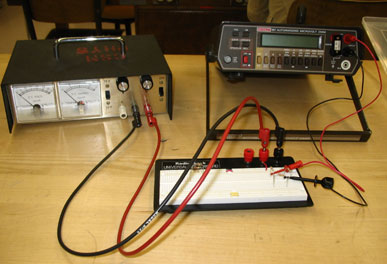
Set up your voltage source to supply four volts. Set your DMM to voltage and take a direct measurement. When you have verified 4 volts, remove your DMM and set it to measure current (mA). Grab a selection of 6 or 7 resistors, none less than 100 ohms. Wire up a single resistor to your power supply and DMM. One wire should go from the power supply to the resistor, then the other end of the resistor should go to the DMM, and the DMM should close the loop and go back to the power supply. You lab instructor will show you one of these circuits in the pre-lab lecture. Measure the current going through the resistor at four volts. Switch in the rest of the resistors one by one. Do you see a confirmation of the name? As you get higher resistances, do you get lower currents?
Plot the curve of currents as a function of resistance, what does the graph look like? Hopefully it confirms the following equation:
ΔV = I R
This is known as Ohm's Law. We can verify it by selecting three resistors, each greater than 1000 ohms, and then plot I as we vary ΔV. These should be nice straight lines. Do the slopes match your expectations?
Circuits with Multiple Resistors
The next thing that gets looked as it what happens to the situation when we add more or more resistors to what we already have. Start with the most basic problem, how does a second resistor affect the circuit? It turns out this is a more complicated problem than one might think, as there are two ways a second resistor can be added. Let's look at each of these in turn.
In our original one resistor circuit, we have the power supply hooked up to the resistor. Let's decide that we want to measure the current coming out of the power supply, so we insert the DMM as a current meter between the power supply and the resistor. Now let's add a second resistor and see how this affects the current in the circuit. How shall we wire in the second resistor? Wire in the second resistor so that the tips of the two resistors are connected to each other and the tails are connected to each other. Since this will cause the resistors to line up side-by-side, this is called a parallel circuit. Does the current from the power supply go up, go down, or stay the same? Does this mean that the resistance in the circuit went up, went down, or stayed the same?
The is another way to wire in the second resistor. Undo your first circuit, and instead wire the "tip" of the second resistor and to the "tail" of the first. This is called a series connection. Does your current go up or down, or stay the same? Does this mean that the resistance in the circuit went up, went down, or stayed the same?
Now we should investigate these cases in more detail. Since we currently have a series circuit wired up, we can start there. Remove your DMM from the circuit so you can use it as a voltage meter. Once the circuit is re-wired, measure the voltage across the power supply. Then measure the voltage across each resistor. Do your results of the voltages across the combination of resistors makes sense when compared to the voltage across the power supply? Do the voltages across each resistor make sense when compared to the current in the circuit? Explain. Add in a third resistor in series, and before you make any measurements, predict what you will find. Do your measurements match your predictions? Can you determine a rule for how the voltages behave? For how the current works in the circuit? How the resistances combine to form an overall resistance for the circuit?
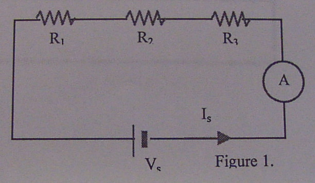
Figure 1 - Measuring Current in a Series Circuit
Now let's turn around and apply the same logic to the parallel circuit. Wire up a two resistor parallel circuit. Take the DMM and check the voltage across the power supply and each of the resistors. What is the pattern? Use Ohm's Law to predict the current through each resistor. Measure the current by hooking up the DMM as a current meter after each resistor (taking care to measure only the current from that resistor, not from the combination). Does the answer make sense? Now measure the current from the power supply, does this also make sense given the currents through each resistor? Add in a third resistor in parallel? What will the voltage across it be? What will the current through it be? Can you find rules describing the voltage, current and combined resistance in parallel circuits?
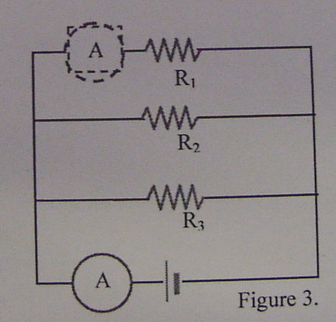
Figure 2 - Measuring Current in a Parallel Circuit
Write up your observations and conclusions in your lab notebook.
Source: https://foothill.edu/psme/marasco/4blabs/ohmslaw_one/
0 Response to "Testing Ohm's Law Experiment"
Post a Comment